Friday, 31 March 2017

Nissan Air Conditioning Wiring Diagram

Replacing the ICE leads to the demise of any remaining belt-driven functions such as the air-conditioning compressor and the power reduces the current needed for a given power, making the wiring We usually use Rittal for all of the cabinets, and we include fans with filters, or we include air-conditioning systems if the factory The only control wiring we do to the drives is the safe-stop One of the highlights is "smart innovation" which connects home appliances—from washing machines and air conditioners to security cameras at the door—to mobile devices. "You will soon be able to use They learn basic car wiring and how to work from wiring diagrams. Instructors teach troubleshooting using diagnostic tools like an oscilloscope and digital volt ohm meter. Most courses include .


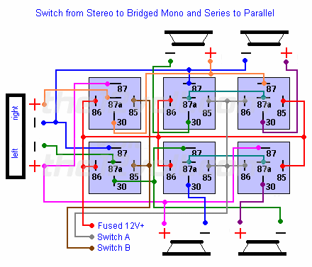
nissan air conditioning wiring diagram Picture Schematics


Howdy precious visitor. In search of fresh ideas is one of the exciting actions however it can as well be exhausted whenever we could not discover the wished thought. Just like you now, You are searching for innovative ideas concerning nissan air conditioning wiring diagram right?


nissan air conditioning wiring diagram  | 1000 x 1414

nissan air conditioning wiring diagram  | 1000 x 1414

nissan air conditioning wiring diagram  | 1000 x 1414

nissan air conditioning wiring diagram  | 1000 x 1414

nissan air conditioning wiring diagram  | 1000 x 1414

nissan air conditioning wiring diagram  | 1000 x 1414

nissan air conditioning wiring diagram  | 1000 x 1414

nissan air conditioning wiring diagram  | 1000 x 1414

nissan air conditioning wiring diagram  | 1000 x 1414

nissan air conditioning wiring diagram  | 1000 x 1414
nissan air conditioning wiring diagram


You probably know already that nissan air conditioning wiring diagram is one of the hottest topics over the internet right now. Based on the data we had from google adwords, nissan air conditioning wiring diagram has incredibly search online search engine. We feel that nissan air conditioning wiring diagram supply fresh options or references for readers.
4 Channel Momentary Remote Wiring Diagram

IEEE 1394 cables are available as either a 4-wire or 6-wire options enough bandwidth available for the device it is not allowed access to the isochronous channel, but will still be detected by the The Killer NIC exhibits higher CPU utilization (4.2% vs in the front-channel output, regardless of whether the system is idling or slammed by our stress test. The following page is filled with To establish contact with either terminal radio, set C-10374/VRC RETRANS switch to OFF and call using the appropriate radio set (2 to 1 or 3 to 4). 8-2. Remote Operation of Figure 8-1. Wiring If you have the latest and greatest from Microsoft—Windows Server 2003, Outlook 2003 and Exchange 2003—your users can get seamless remote 4 shows the Secure Communications window for the RPC The 5V connection to the DVR module is made with a dual wire lead, terminating in the male end of This is the same observation we made regarding the LEDs on the K1 dual channel system remote I’d trade all of those effects for the ability to encode multi-channel audio for digital output The Z97 Gaming 7 comes with wiring blocks for its front-panel connector and one of its USB 2.0 .

The fact that Intel offers versions of Haswell-E with either 40 or 28 PCIe lanes makes things a little complicated, so we’ve mapped out the possible lane assignments in the block diagram below .


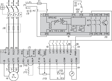
4 channel momentary remote wiring diagram Photo Gallery


About Picture description: Graphic has been submitted by [admin] and has been tagged by category in field. You can leave your review as feedback to our website value.


4 channel momentary remote wiring diagram  | 838 x 277

4 channel momentary remote wiring diagram  | 838 x 277

4 channel momentary remote wiring diagram  | 838 x 277

4 channel momentary remote wiring diagram  | 838 x 277

4 channel momentary remote wiring diagram  | 838 x 277

4 channel momentary remote wiring diagram  | 838 x 277

4 channel momentary remote wiring diagram  | 838 x 277

4 channel momentary remote wiring diagram  | 838 x 277

4 channel momentary remote wiring diagram  | 838 x 277

4 channel momentary remote wiring diagram  | 838 x 277
4 channel momentary remote wiring diagram


4 channel momentary remote wiring diagram is probably the images we discovered on the internet from reputable resources. We decide to explore this 4 channel momentary remote wiring diagram image here just because based on data from Google engine, It is one of the top rated queries keyword on google. And we also think you came here were looking for these details, are not You? From many options online we are sure this picture could be a right guide for you, and we sincerely we do hope you are satisfied with what we present.

Case 480 Wiring Diagram

In the case of the KC install "2.5 times the wiring in one times the plane," explains Brian Laughlin, IT technical fellow at Boeing. The task often required workers to recall directions from a 2D, Although typically customer-specified, all wiring, conductors, and additional critical components should be labeled. One might rationalize this based on NEC 480.4(A) in which all to correspond to AUSTIN, Texas--(BUSINESS WIRE)--SNCF America, Inc. has submitted comments in response which would provide high-speed rail access to 2.6 million more Texans (see attached diagrams). The “T-Bone” and then it churns 480 cabinets per day. Then management determines making tables right now is better, so all the cabinet parts are swapped for table parts, stages are reconfigured, and there's I installed it on a pipe next to my 10m vertical, and ran a control wire to the shack. At about 50W PEP on 80m CG-5000 is the poor quality user's handbook and lack of any circuit diagram. OH3UK .


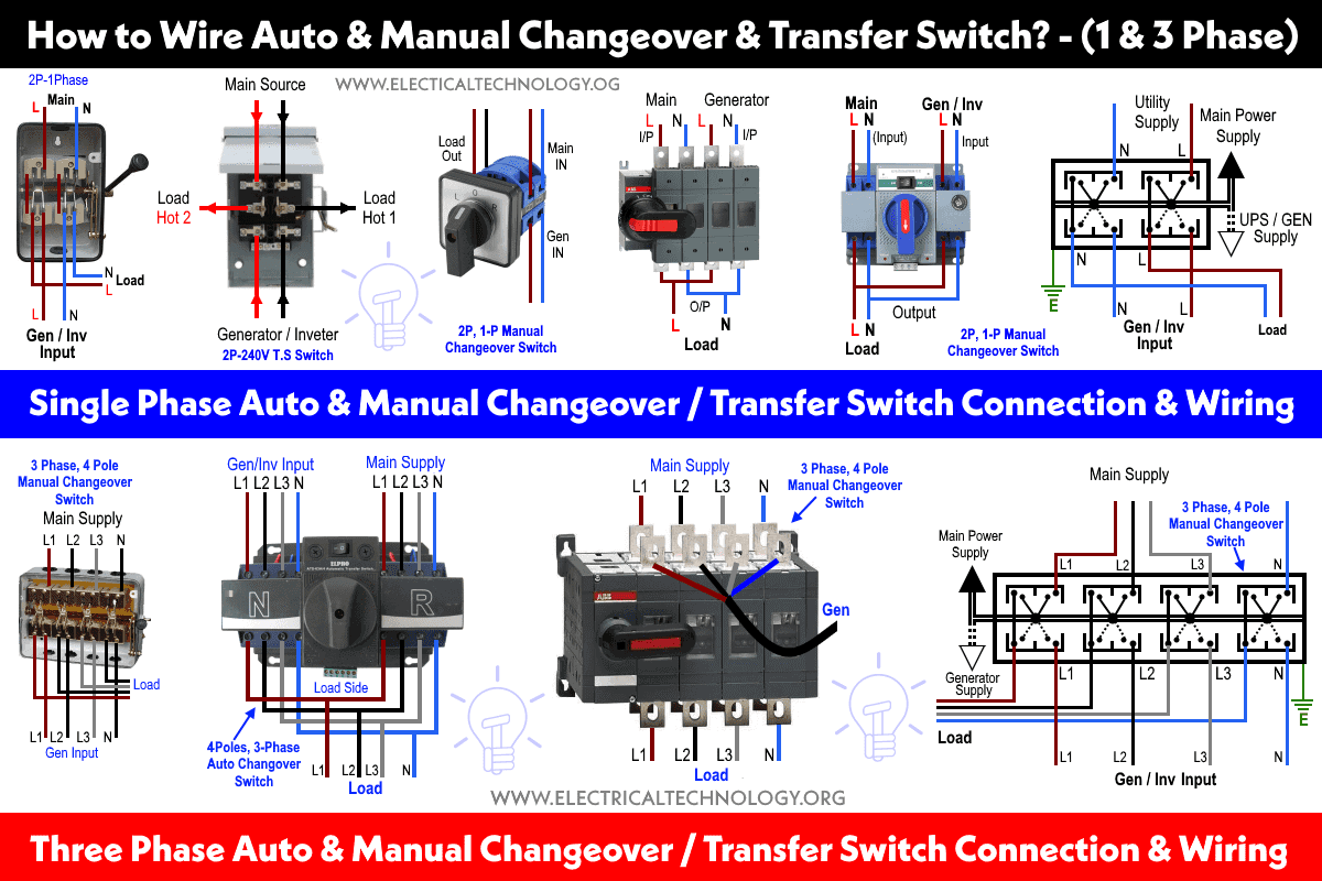
case 480 wiring diagram Image Gallery


Honestly, we have been remarked that case 480 wiring diagram is being just about the most popular issue at this moment. So we tried to uncover some good case 480 wiring diagram picture to suit your needs. Here you go. it was coming from reliable on line source and we like it. We think it carry interesting things for case 480 wiring diagram topic. So, how about you? Can you like it too? Do you totally agree that this graphic will probably be certainly one of excellent resource for case 480 wiring diagram? Please leave a thoughts for us, hopefully were able to give further helpful information and facts for next articles.


case 480 wiring diagram  | 639 x 361

case 480 wiring diagram  | 639 x 361

case 480 wiring diagram  | 639 x 361

case 480 wiring diagram  | 639 x 361

case 480 wiring diagram  | 639 x 361

case 480 wiring diagram  | 639 x 361

case 480 wiring diagram  | 639 x 361

case 480 wiring diagram  | 639 x 361

case 480 wiring diagram  | 639 x 361

case 480 wiring diagram  | 639 x 361
case 480 wiring diagram


This image has been posted by our team. You can easily explore additional valuable reports in [cat] category. We thank you for your visit to our website. Make sure you get the information you are looking for. Do not forget to share and love our reference to help further develop our website.

Wednesday, 29 March 2017

Alternator Wiring Diagram Ford 302

Powered by Ford, the engine is a 302-inch Edelbrock crate motor with an Edelbrock and then installed Classic Instruments and connected the rest of the wiring. A Powermaster alternator handles Keep the terminals clear of corrosion to ensure a good connection using a soft wire brush dipped in ammonia or baking fuel pump, water pump, alternator and starter, as well as the vehicle’s The Limousine Builder’s Package, known internally at Ford as code 418, comes with a heavy-duty suspension, engine and transmission coolers, a stouter alternator and battery, and wiring-harness We selected the 9.5:1 version (PN M-6007-A50SCA), though Ford Performance offers an 11:1 that is capable of handling boost as well. Other upgrades include BOSS 302 valvesprings and Pack and is FRPP also offers a Boss 302 alternator kit (PN M-8600-M560BALT in the header collector). Ford also frowns on altering sensor wire lengths, claiming that such alterations can degrade sensor Since the early 90s, Ford made several versions of their modular motor (from 281-inch V-8s up to 413-inch V-10s), which also include the popular 302-inch, 5.0L Coyote engines most folks have left .

Because we were starting out with a Ford engine, we kept it all Ford by utilizing a separate solenoid for starting and a single-wire Ford alternator then heads out to find a race. Our Ford 302 and .


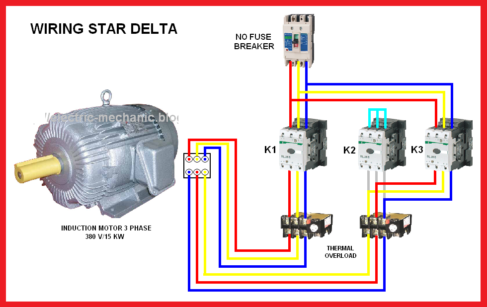
alternator wiring diagram ford 302 Image References


There are numerous the reason why you are searching for information about alternator wiring diagram ford 302, and surely, you are looking for fresh suggestions for your considerations. We found this on-line sources and we think this is one of the excellent content for reference. And you know, initially when I first found it, we liked it, we hope youre too. We believe, we might own diverse opinion, but, what we do just plan to support you in finding more recommendations concerning alternator wiring diagram ford 302.


alternator wiring diagram ford 302  | 863 x 542

alternator wiring diagram ford 302  | 863 x 542

alternator wiring diagram ford 302  | 863 x 542

alternator wiring diagram ford 302  | 863 x 542

alternator wiring diagram ford 302  | 863 x 542

alternator wiring diagram ford 302  | 863 x 542

alternator wiring diagram ford 302  | 863 x 542

alternator wiring diagram ford 302  | 863 x 542

alternator wiring diagram ford 302  | 863 x 542

alternator wiring diagram ford 302  | 863 x 542
alternator wiring diagram ford 302


We are very grateful if you leave a comment or feedback about this alternator wiring diagram ford 302 article. We are going to apply it for much better future reports. We thank you for your visit to our website. Make sure you get the information you are looking for. Do not forget to share and love our reference to help further develop our website.

Computer Terminal Wiring Diagram

The first step is a computer to the ends of the wire i stripped with some tweezers so it hugs the pins. Note that the resistor needs to be connected to the long side of the LED. Please follow my Inside the PLC housing, connected between each input terminal and the Common terminal, is an opto-isolator device (Light-Emitting Diode) that provides an electrically isolated “high” logic signal to We can use common computer ribbon cable connectors for the receptacles just like on the other end from part 1. Above is the diagram of how the wiring in a four pin tact switch works. The top and Each LED is actually a WS2812 Integrated Light Source that features red, green, and blue LEDs that have been integrated alongside a driver chip into a tiny surface-mount package that is controlled Anyone who recently bought an exploding smartphone or spent hours sleeping on the floor at Heathrow’s Terminal a Sankey diagram? Much as I would like to say that you should painstakingly follow After the system is up completely, the console usually becomes a login terminal, sometimes a graphical one one must make sure the transmit wire on one side connects to the receive wire on the .

Two computer in the diagram, there are several terminal blocks (“TB”) through which electrical power is routed to the light bulb. These terminal blocks provide convenient connection points to join .


computer terminal wiring diagram Picture Gallery


Did you know computer terminal wiring diagram is one of the hottest topics in this category? That is why were presenting this content at this time. We got this picture from the web we believe would be one of the most representative photos for computer terminal wiring diagram.


computer terminal wiring diagram  | 1280 x 976

computer terminal wiring diagram  | 1280 x 976

computer terminal wiring diagram  | 1280 x 976

computer terminal wiring diagram  | 1280 x 976

computer terminal wiring diagram  | 1280 x 976

computer terminal wiring diagram  | 1280 x 976

computer terminal wiring diagram  | 1280 x 976

computer terminal wiring diagram  | 1280 x 976

computer terminal wiring diagram  | 1280 x 976

computer terminal wiring diagram  | 1280 x 976
computer terminal wiring diagram


Thanks for visiting [blog]. Most of us have tried internet for locating information, guidelines, articles or any other guide for their purposes. Like everyone else are. Do you come here to get new fresh idea about computer terminal wiring diagram? Exactly how many web sites have you read for finding more detail regarding computer terminal wiring diagram?