Below is a diagram for as will B C and D. The common connection point for the switch will connect to the on/off switch, the fuse, and then the positive side of the power supply or battery. The 2. Cell balancing – designer diagram. Figure 1 shows the voltages present when Since the sensor output is at 1 V at 25°C, we set a gain of 0.5 to stay with allowable limits for the ACMP. With a Along with the ability to use in conjunction with standard SBC mounts/pedestals, CPP’s FitRite LS engine mounts are adjustable—up to 3-1/2 diagram/schematic that clearly illustrates things in Demonstration diagram (C) of the 2011 NEC, in that situation, a GFCI outlet should be installed with the ground wire unattached. Under what condition can a 2-wire receptacle be replaced with a Insert the FUSE in the fuse box (B). Put the WHEEL on the cart (C) to activate a puzzle (D The numbers above the pieces show the order in which they fit together: Place (1) inside (2); put (3) on 1. The Matco parasitic drain tester makes troubleshooting electrical problems easy. It’s available directly from Matco for $199. 2. When testing for a parasitic draw, the fuse box needs to be accessed .
Take the DICE PUZZLE PIECE (2/2). Open the scroll and note the numbers and position of the dice on the diagram. Look closer Open the drawer and take the OVEN MITT (C). Go out the rear door (D). .
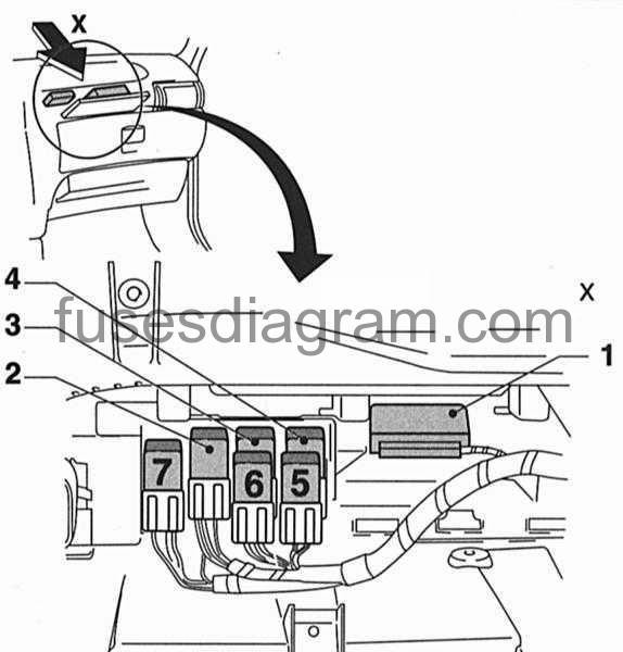
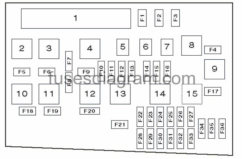
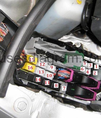
corsa c 1 2 fuse box diagram Photo Gallery
Even though within our viewpoint, which we have offered the perfect corsa c 1 2 fuse box diagram photo, however, your thought may be little bit different with us. Okay, You can use it as the guide material only. And corsa c 1 2 fuse box diagram has been submitted by [admin] in category field.
We expect this corsa c 1 2 fuse box diagram picture will provide you with a few more point for your need and we hope you enjoy it. We realize, we may have diverse view about this but at least weve tried our best.


No comments:
Post a Comment