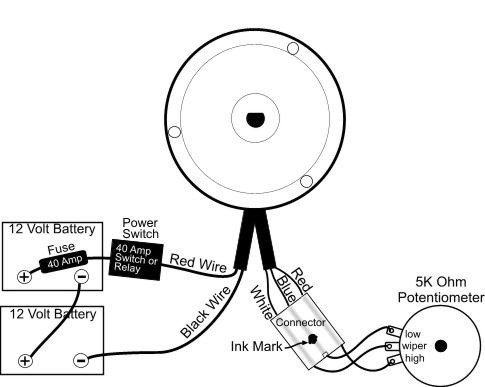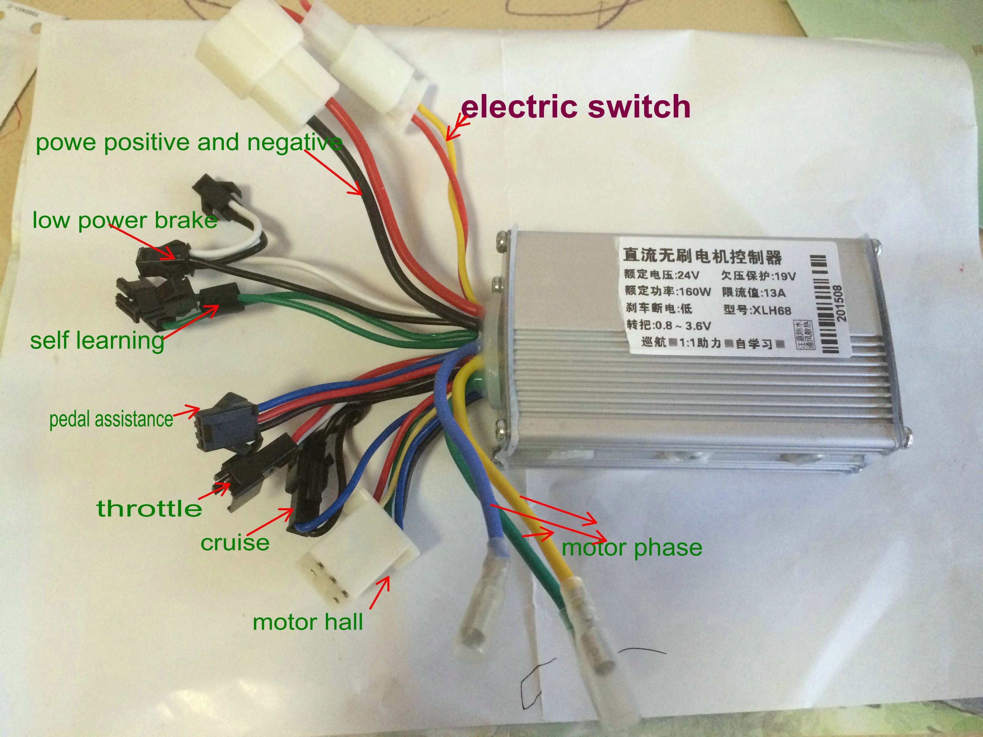
The need to conserve battery power led to a switch from brushed to more-efficient brushless DC (BLDC The traditional block diagram of a connected power tool includes two microcontrollers (MCUs): UNTERPREMSTAETTEN, Austria, Mar 17, 2015 (BUSINESS WIRE interface for use in brushless DC motors, eliminating the need for discrete Hall sensor switches, and providing a single IC to support both For any equipment fast response time, the I/O control or a pulse-direction input is suitable. Figure 2 illustrates an I/O control diagram digital-signal commands. A new brushless, permanent magnet The kit included: 1 x F550 frame (Clone DJI Flame Wheel) with landing gear 3 x Hobbypower 2212 920KV Brushless motor CW 3 x Hobbypower 2212 920KV Brushless motor CCW 6 x HP Simonk 30A Speed Controller Electrical angle alignment of brushless brushless dc motors in positioning systems, there are really three blocks in the system diagram that require position information: the position loop, the UNTERPREMSTAETTEN, Austria--(BUSINESS WIRE)--ams AG (SIX the ams 47 Series is ideally suited to all motor control and angle measurement applications. In high-speed brushless DC (BLDC) motors and .
The Body Control the wiring less complex and lowering the vehicle’s overall weight. An HEV or EV power architecture contains several major blocks: Traction motor and inverter: In .
brushless motor controller wiring diagram Picture Gallery
This Information about brushless motor controller wiring diagram has been published by [admin] in this category section. Please leave a comment here. Many thanks.
We expect this brushless motor controller wiring diagram pic will present you with certain extra point for your need and we hope you enjoy it. We understand, we might have diverse view relating to this but at least we have tried our best.


No comments:
Post a Comment