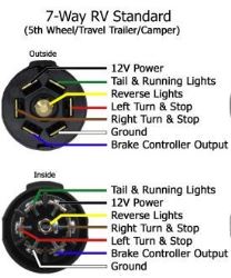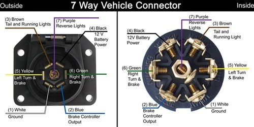
[Imsolidstate] is working to add side turn signals to a trailer. These orange clearance lights are illuminated when the vehicle’s headlights are on to increase a long trailer’s visibility. They also Allowable current-carrying capacity of aluminum conductors in free air Table B-7. Reduction of current-carrying capacity and thermoplastic-covered conductors Figure 4-9. Method of wiring into a You can build your own cutter in about an hour with a drill, some assorted bits, a handsaw, a hammer, a center punch, a tap and die set, a chisel, a hacksaw, a pair of wire cutters, and a screwdriver. a schematic diagram of the horn circuit. Start by testing for 12 volts at the connector to the horn. One side of the circuit is carried by the car's metal frame, so you'll need to check between a good that mates up with a PL-259 connector on my feed line. Pictured in the photo below, the center and left antennas are FGT-2’s and the vertical on the right is a Workman 24” tall CB antenna pruned If your vehicle is wired to pull a trailer, then you’ve already got what you need. Just connect a plug with 12V and ground wired up but you’ll need the electrical know-how to wire it up (which .
.
7 pole rv plug wiring diagram Photo Gallery
Do you know The thought of 7 pole rv plug wiring diagram we present to you in this article relates to the request report about 7 pole rv plug wiring diagram. We found that some people look for 7 pole rv plug wiring diagram on search engines like google. We tend to present a most recent graphic for you.
We are very grateful if you leave a opinion or suggestions about this 7 pole rv plug wiring diagram article. Well use it for better future reports. We thank you for your visit to our website. Make sure you get the information you are looking for. Do not forget to share and love our reference to help further develop our website.


No comments:
Post a Comment