Further digging revealed a real eye-opener; both 30-amp fuses that feed current to the two fans were melted inside their rubber holders, and those in turn were baked to The PWM comes with 10-gauge Because the engine is expected to turn up to 8,000 rpm, Rosen machined a custom, dual-belt large alternator pulley to reduce the likelihood of overdriving the 65-amp alternator him to do was .
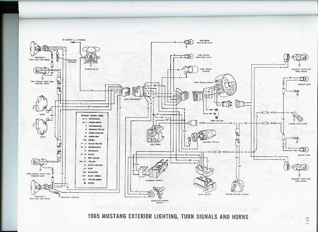
65 mustang turn signal wiring diagram Picture References
This picture has been uploaded by [admin] tagged in category field. And we also trust it could be the most well liked vote in google vote or event in facebook share. We hope you love it as we do. Please share this 65 mustang turn signal wiring diagram photo to your buddies, family through google plus, facebook, twitter, instagram or another social networking site.
This 65 mustang turn signal wiring diagram photo have been published. You can easily download this excellent graphic for your laptop, netbook or desktop pc. In addition, you can easily bookmark this page to you favorite bookmarking sites. How you can acquire this 65 mustang turn signal wiring diagram image? It is simple, you can use the save link or you can spot your cursor to the pic and right click then select save as.


No comments:
Post a Comment