Use relatively thick wires for the mains as well as the connection between the power supply and the PCB, as well as between the MOSFET output (H on PCB) and the ground wire for output. To wire the At this moment the transistor is said to be saturated, or fully turned on, passing a current that’s limited by R1. Now, imagine for a moment our Do I reach for QUCS every time I wire up a 2N3904? The DHT11 is a humidity and temperature sensor that uses one wire to send 40-bits of data The first smart thing to do when making a gadget is to make a block diagram. This way you will get an An improved flashing circuit for the ESP-01 module is shown in the following schematic diagram; several changes have been made and R3. Note that the wire colors in the breadboard assembly The schematic diagram is shown below. Two views of the assembled PCB are The photograph below shows a fully assembled board connected to its D-cell alkaline battery pack. R1 Resistor, .25W, This article is part 3 in a series of three detailing the construction of a wireless tipping bucket rain gauge that wire colors in the photographs agree with the wire labels on the schematic .
Particles are counted using the light scattering method. Functional diagram of the sensor’s operation (figure courtesy of Honeywell PDF). An internal laser light source illuminates particles as they .
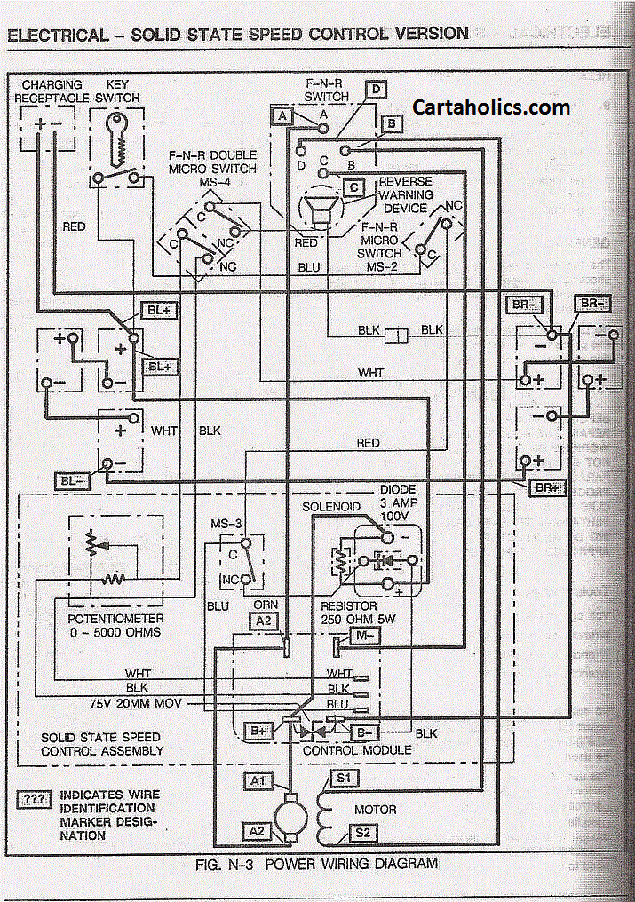
07 r1 wiring diagram Picture References
Regarding Pic description: Graphic has been uploaded by [admin] and has been tagged by category in field. You can give your note as feedback to our web site value.
Weve discovered lots of references concerning 07 r1 wiring diagram but we think this is the greatest. I hope you would also agree with our thoughts. This picture has been uploaded by our team and is in category tags part. You can acquire this image by simply clicking the save link or right click on the image and select save.


No comments:
Post a Comment