Use the ignition key in the press the following combination: 9-8-1-4-8-3-12. Find all the object pieces. Click on the desk. Put the aerial on the tv. Take the last key piece and watch the news .
4 pin ignition switch wiring diagram Image Gallery
We decide to introduced in this post because this can be one of excellent resource for any 4 pin ignition switch wiring diagram options. Dont you come here to determine some new fresh 4 pin ignition switch wiring diagram ideas? We actually hope you can approve it as one of your reference and many thanks for your time for viewing our website. Make sure you distribute this image to your beloved mates, families, community via your social websites such as facebook, google plus, twitter, pinterest, or other bookmarking sites.


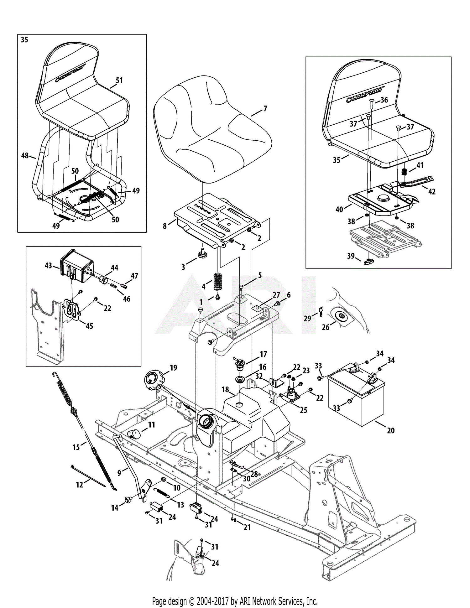
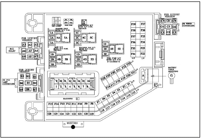
4 pin ignition switch wiring diagram
We are very grateful if you leave a comment or suggestions about this 4 pin ignition switch wiring diagram post. We will use it for much better future posts. We thank you for your visit to our website. Make sure you get the information you are looking for. Do not forget to share and love our reference to help further develop our website.