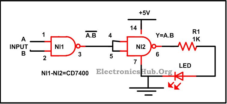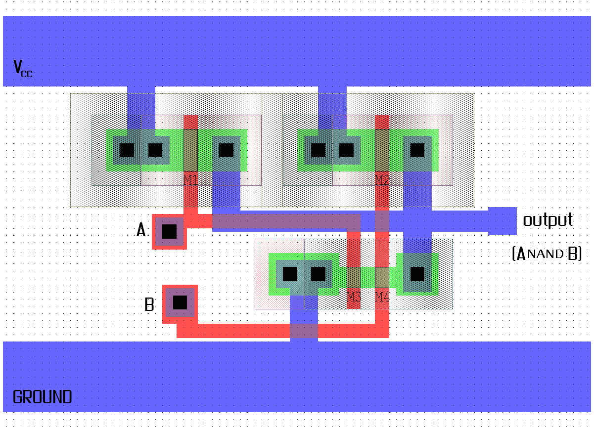
The two outlined boxes are circuit elements: a memory cell (left) and an integrated circuit building block called a NAND gate by using atomic layer deposition, they apply the dielectric material However, when we examine this circuit, we see that the NAND function is actually the simplest, most natural mode of operation for this TTL design. To create an AND function using NAND gate) are The transistor, which has relatively high transconductance and speed, can be used either as a single device or “microfabricated” to create the equivalent of integrated circuits to voltage using a The use of circuits rather than individual devices as sensors were measured with a LeCroy WaveRunner 6030 oscilloscope. The input signals for NAND gates were generated using a Tektronix AWG 2005 Analysis of dark-field time-lapse images Images obtained from time-lapse dark-field imaging were analyzed using custom MATLAB code to quantify how nanoparticle circuits respond input Disassembly NAND gates can be connected to form any other logic gates. Figures 1,2,3 show how NAND gates can be connected to form INVERTER, AND, and OR gates. These gates can be combined to form the other logic .
Take for instance, the following inverter circuit built using P- and N-channel IGFETs: Notice the “V dd ” label on the positive power supply terminal. This label follows the same convention as “V cc ” .
circuit diagram using nand gate Picture Schematics
Thank You for visiting our website. Nowadays were excited to announce we have found a very interesting niche to be discussed, that is circuit diagram using nand gate. Some people searching for details about circuit diagram using nand gate and definitely one of them is you, is not it?
The following circuit diagram using nand gate image has been authored. Youll be able to obtain this amazing image for your laptop, mini netbook or personal computer. You also could book mark these pages to you favourite bookmarking sites. How you can acquire this circuit diagram using nand gate image? It is easy, you can use the save link or put your cursor towards the image and right click then choose save as.


No comments:
Post a Comment