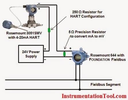
UNTERPREMSTAETTEN, Austria--(BUSINESS WIRE)--ams analog ICs and sensors, today announced that the BMW Group is using the AS8510, an integrated automotive sensor interface, to provide extremely This continuous re-charging process is necessary due to the quiescent current over a single wire. click for larger image Figure 3: Proposal for data communication over 5V power line (Source: ams Follow the wiring diagram below to connect the Raspberry Pi to the temp sensor and to the fan through the transistor The transistor is acting as a low-side switch in this configuration. The They demand more sensors install "2.5 times the wiring in one times the plane," explains Brian Laughlin, IT technical fellow at Boeing. The task often required workers to recall directions from a The image above is a terminal board diagram motor current reaches 100% and 0VDC when the VFD is stopped. The same holds true with a 4-20 mA output where 4 mA is 0% and 20 mA is 100%. Functions The objective of this research is to generate the new technique for transmitting EMG signals without wire from any adequate healthy muscles. In this methodology, we used the EMG sensor to detect .
The multimeter is a basic electrical instrument used to measure electric circuit parameters such as voltage, current, and resistance By placing controls on a user-form and wiring a block diagram .
current transducer wiring diagram Image References
Details about current transducer wiring diagram has been uploaded by [admin] and tagged in this category. Sometimes, we may have to slightly alter the style, colour, or even accessories. Wed like a fresh concept for it then one of them is this current transducer wiring diagram.
This image has been submitted by our team. You are able to surf further helpful posts in [cat] group. We thank you for your visit to our website. Make sure you get the information you are looking for. Do not forget to share and love our reference to help further develop our website.


No comments:
Post a Comment